weeDrumster

Another new project I started this month and actually one that made it to some sort of working state, which is not very common to me (don’t even remind me of ATTAG and that Kiln thing (horrible code). I know I have to get back to these one day but now this came to my mind and it had to be done. 😉

Download v0.6 for Windows here:

weeDrumster v0.6

The 3D-print files are here:

weeDrumster 3D printable files

What is weeDrumster?

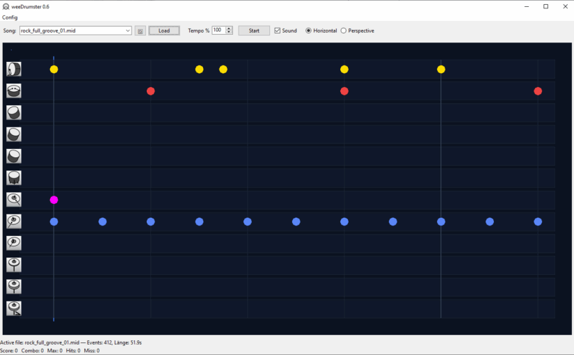
You probably can already guess from the screenshots. I wanted to create some sort of trainer for my vdrum digital Drumkit. Many probably know the concept from some games like Rockband, BandHero or Beatsaber, the notes scroll through the screen and you have to hit them at the right moment. The drumkit already comes with some similar thing as subscription service. (I forgot the name.) They put a lot of efford in it to create some training modes but the app used such a small area of the screen, that it was a pain to follow it and play the drums meanwhile.

weedDrumster simply connects via USB to the drumkit and reads your hits. You can load any mid file you want (put them into the /mid path), though many are badly edited or buggy, often the drum part isn’t set to channel 10, so they might sometimes sound weird or miss some of the drum parts. I tried to fix these problems but gave up and decided it is easier to pick some good midi files, the internet is full of those for free. If you don’t want to search for those, I also added a rather stupid midi pattern generator that spits out some random drum part patterns and stores them in the /mid path.

You can set various parameters, pre-roll, offset, play with sound or without, play all or just the drums or only all other instruments. You can mute a drum track by clicking on it in the horizontal mode or on the icon in perspective mode

The perspective mode.

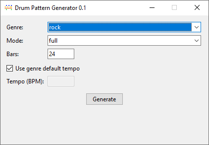
The pattern generator, pretty self-explanatory.

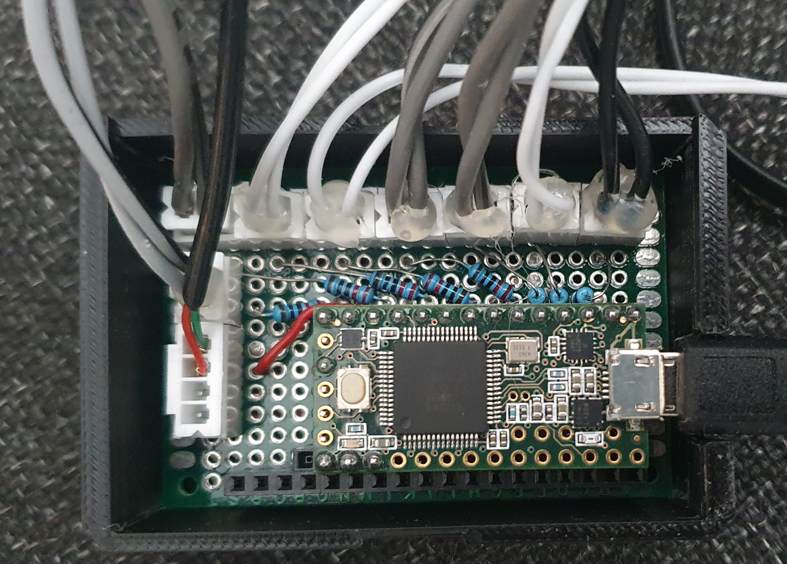
Now to the more crazy part, while getting the software done I thought it isn’t good enough to show the notes on the screen, why not showing them directly at the drums? So I remembered I had an unused Teensy 3.2 microcontroller somewhere waiting for some usage. I didn’t know much about it just that it was neat for building controllers that can be connected via. USB. To my surprise it was perfectly made for usage with midi, low latency, many I/O pins. Perfect.

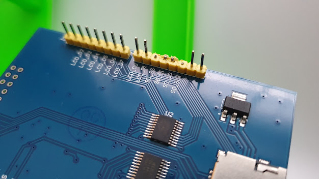
The circuit itself is pretty straight forward, I just soldered a bunch of Dupont connectors to a circuit board and connected them to GND with one pin and along 220R resistors to some pins.

Pins 1,2,3,4,6,8,10,12. Due to space issues I left out those in between, but you can use any of these, just remember the 13 is also the internal LED of the Teensy 3.2.

If you want to have more drums, want to split HiHat into open,closed,pedal or Ride into bell,rim,bow you need more LED of course and modify the code. I left those on one LED, because I thought it would get too chaotic anyway.

So circuit description for each LED:

LED (long leg) —> [220R] –> pin

LED (short leg) –> GND

Of course you can modify the resistor to the exact value matching your LED, I was too lazy and gave them all the same which works fairly okay with 220R

In addition I added a switch to pin 14 and connected it to a foot pedal. This one simulates space for start/stop so I don’t have to reach over to the notebok all the time to restart the song/pattern.

Circuit: GND–>switch–>Pin 14, no further magic here. I used a cheap microswitch and soldered it to an empty circuit board. Don’t know how long it will last, we will see. Of course you can also just buy a ready made foot pedal switch, there should be some.

// ------------------------------
// Teensy Drum-LED Trigger + Start/Stop-Button 
// ------------------------------

#include <Keyboard.h>  // for the foot pedal / space key similation

#include "usb_names.h"

// Check all midi modes so I can give the Teensy a decent name that appears in weeDrumster port selection (I don't know what the internal name for "all of the above" is) :
#if defined(USB_MIDI) || defined(USB_MIDI_SERIAL) || defined(USB_MIDI4_SERIAL) || defined(USB_MIDI_AUDIO_SERIAL) || defined(USB_MIDI_RAWHID) || defined(USB_MIDI_JOYSTICK) || defined(USB_MIDI_RAWHID_SERIAL) || defined(USB_MIDI_AUDIO) || defined(USB_KEYBOARDONLY_RAWHID_MIDI) || defined(USB_MIDI_SERIAL_HID) || defined(USB_ALLMINI) || defined(USB_EVERYTHING)

// port name:
#define PRODUCT_NAME   {'L','E','D','O','u','t'}
#define PRODUCT_NAME_LEN  6

#define MANUFACTURER_NAME {'T','h','e','p','i','x','e','l'}
#define MANUFACTURER_NAME_LEN 8

struct usb_string_descriptor_struct usb_string_product_name = {
  2 + PRODUCT_NAME_LEN * 2,
  3,
  PRODUCT_NAME
};

struct usb_string_descriptor_struct usb_string_manufacturer_name = {
  2 + MANUFACTURER_NAME_LEN * 2,
  3,
  MANUFACTURER_NAME
};

#endif

#define NOTE_KICK   36
#define NOTE_SNARE  38
#define NOTE_HH     42   // all HiHat-Variants  appear as 42, you can split those up and add more LED to your kit of course
#define NOTE_RIDE   51   // all Ride-Variants appear as 51, same here 
#define NOTE_CRASH  49
#define NOTE_TOM1   48
#define NOTE_TOM2   45
#define NOTE_TOM3   43

// LED Pins
#define LED_KICK   1
#define LED_SNARE  2
#define LED_HH     3
#define LED_CRASH  4
#define LED_RIDE   6
#define LED_TOM1   8
#define LED_TOM2   10
#define LED_TOM3   12

// Button-Pin
#define BUTTON_PIN 11                                                                                

// internal Teensy LED
#define LED_INTERNAL  13

// Full brightness
#define PULSE_BRIGHTNESS  255
#define DECAY_SPEED       5      

int ledLevel[8] = {0};
                         
// Button-handling
bool lastButtonState = HIGH;
unsigned long lastButtonChange = 0;
const unsigned long debounceMs = 25;

// Internal LED blink
bool blinkState = false;
unsigned long lastBlink = 0;
const unsigned long blinkInterval = 120;  //blink speed

void setup() {
  // LED Pins
  pinMode(LED_KICK,  OUTPUT);
  pinMode(LED_SNARE, OUTPUT);
  pinMode(LED_HH,    OUTPUT);
  pinMode(LED_CRASH, OUTPUT);
  pinMode(LED_RIDE,  OUTPUT);
  pinMode(LED_TOM1,  OUTPUT);
  pinMode(LED_TOM2,  OUTPUT);
  pinMode(LED_TOM3,  OUTPUT);

  // internal LED
  pinMode(LED_INTERNAL, OUTPUT);
  digitalWrite(LED_INTERNAL, LOW);

  // Button
  pinMode(BUTTON_PIN, INPUT_PULLUP);

  // prepare "Keyboard"
  Keyboard.begin();
}

void loop() {

  // read MIDI
  while (usbMIDI.read()) {
    if (usbMIDI.getType() == usbMIDI.NoteOn &&
        usbMIDI.getData2() > 0) {

      triggerLed(usbMIDI.getData1());
    }
  }

  // LEDs soft off
  for (int i = 0; i < 8; i++) {
    if (ledLevel[i] > 0) {
      ledLevel[i] -= DECAY_SPEED;
      if (ledLevel[i] < 0) ledLevel[i] = 0;
    }
  }

  // write LEDs 
  analogWrite(LED_KICK,  ledLevel[0]);
  analogWrite(LED_SNARE, ledLevel[1]);
  analogWrite(LED_HH,    ledLevel[2]);
  analogWrite(LED_CRASH, ledLevel[3]);
  analogWrite(LED_RIDE,  ledLevel[4]);
  analogWrite(LED_TOM1,  ledLevel[5]);
  analogWrite(LED_TOM2,  ledLevel[6]);
  analogWrite(LED_TOM3,  ledLevel[7]);

  // watch button
  handleButton();

  delay(4);
}

void triggerLed(int note) {
if (note == NOTE_KICK)        ledLevel[0] = PULSE_BRIGHTNESS;
else if (note == NOTE_SNARE)  ledLevel[1] = PULSE_BRIGHTNESS;
else if (note == NOTE_HH)     ledLevel[2] = PULSE_BRIGHTNESS;
else if (note == NOTE_CRASH)  ledLevel[3] = PULSE_BRIGHTNESS;
else if (note == NOTE_RIDE)   ledLevel[4] = PULSE_BRIGHTNESS;
else if (note == NOTE_TOM1)   ledLevel[5] = PULSE_BRIGHTNESS;
else if (note == NOTE_TOM2)   ledLevel[6] = PULSE_BRIGHTNESS;
else if (note == NOTE_TOM3)   ledLevel[7] = PULSE_BRIGHTNESS;

}

void handleButton() {
  int state = digitalRead(BUTTON_PIN);
  unsigned long now = millis();

  // make sure your button isn't nervous ;-) 
  if (state != lastButtonState && (now - lastButtonChange) > debounceMs) {
    lastButtonChange = now;
    lastButtonState = state;

    if (state == LOW) {
      sendSpaceKey();
    }
  }

  // flash internal LED when button pressed
  if (state == LOW) {
    if (now - lastBlink > blinkInterval) {
      lastBlink = now;
      blinkState = !blinkState;
      digitalWrite(LED_INTERNAL, blinkState ? HIGH : LOW);
    }
  } else {
    // internal LED of when button released
    digitalWrite(LED_INTERNAL, LOW);
  }
}

void sendSpaceKey() {
  Keyboard.press(' ');
  delay(10);
  Keyboard.release(' ');
}
Make sure your Teensyduino IDE USB Type is set to "All of the above" because there is no keyboard+midi preset.

That is what it looks like, well sort of. Not many of the LED are visible but you get the idea. Some ring-lights around the snare and tom would be a cool thing. If you have an idea that doesn’t need an external psu, let me know.

That’s it, let me know what you think.

Genealogie Web App RootSoup

Vor einer Weile habe ich einmal eine Genalogie App fürs Web gebastelt. Es gibt so einige Programme und Webscripte, aber die haben mir alle nicht wirklich zugesagt. Falls jemand Interesse hat, kann man mich unter

frickel[at]thepixel.net

erreichen. Für private Anwendungen gedenke ich das ganze Paket irgendwann einmal kostenfrei zu veröffentlichen. Einen Gastzugang / Demo gibt es hier mit gast/gast, die Schreibrechte sind allerdings deaktiviert:

Auto printing a set of PDF from web on multiple printers.

While I am stuck at the ATTAG project again I had to solve a completely different problem. If you are running an online shop you probably came across the issue that you have to print different types of documents on different printers. Like product labels, invoices, shipping labels. It is pretty annoying if you have to handle multiple orders and every step requires a change of the print settings over and over again. This often leads to documents printed on the wrong printer, paper mess and so on.

So I was looking around if there are some ready-to-use solutions. And yes there are but at insane costs compared to triviality. For a long while we had a working solution that used javascript inside the pdf document to choose the correct printer. But this only worked for Firefox and after the newer generations seem to block this due to security issues.

So actually it is pretty simple but you need to create PDFs of your documents which then can be retrieved. I am not covering this part here. You may do this with FPDF or any other PDF generator on your shop server.

This guide expects WINDOWS to be used.

First step is you need to install these:

  1. A webserver package such as xampp, just the Apache webserver and php will be used
  2. Python (tested with 3.X)
  3. Ghostscript
  4. GSPrint

Since the browsers won’t allow you to execute a program on your local PC you need to let a local webserver do that. In XAMPP control you can set the Apache webserver to autostart with windows. You may have to run XAMPP with adminstrator priviledges for that!

Once you installed it, create a small print.php script containing the following:

<?php 
$pyscript = 'C:\\gs\\print.py'; // the path to python print script
$python = 'python.exe'; // you may need the absolute path of python here, like C:\\programs\\python\\python.exe or wherever you installed it
exec($python." ".$pyscript, $output);
echo "Printjobs started...";
?>

I extracted all the ghostscript / gsprint stuff to C:\gs, put it wherever you like but keep in mind where, you will need it later.

The following is the python script which chooses the correct printer per document and starts the printjob through ghostscript and gsprint. You may also use any other pdf viewer/printer for this which works with command line execution such as the PDF-XChange Viewer.

Of course you have to edit the paths, url and currentprinter according to your settings. Your python may need some packages used here, install them with

pip install requests

pip install win32api

pip install win32print

from windows command line (START-> cmd)

#!/usr/bin/env python
import win32print
import win32api
import requests

GHOSTSCRIPT_PATH = "C:/gs/bin/gswin32.exe"
GSPRINT_PATH = "C:/gs/gsprint.exe"

LOCAL_FILE = "C:/gs/invoices.pdf" 
currentprinter = "Samsung C1810 Series"
url='https://www.yourshopdomain.com/wherever_you_put_the_pdf_there/invoices.pdf'
r = requests.get(url, stream=True)
with open(LOCAL_FILE, 'wb') as f:
	f.write(r.content)
params = '-ghostscript "'+ GHOSTSCRIPT_PATH  +'" -printer "'+currentprinter+'" -portrait -copies 1 "'+LOCAL_FILE+'"'
win32api.ShellExecute(0, 'open', GSPRINT_PATH, params, '.',0)

LOCAL_FILE = "C:/gs/slabels.pdf" 
currentprinter = "BIXOLON SRP-770II"
url='https://www.yourshopdomain.com/wherever_you_put_the_pdf_there/shipping_labels.pdf'
r = requests.get(url, stream=True)
with open(LOCAL_FILE, 'wb') as f:
	f.write(r.content)
params = '-ghostscript "'+ GHOSTSCRIPT_PATH  +'" -printer "'+currentprinter+'"  -portrait -copies 1 "'+LOCAL_FILE+'"'
win32api.ShellExecute(0, 'open', GSPRINT_PATH, params, '.',0)


LOCAL_FILE = "C:/gs/plabels.pdf" 
currentprinter = "Colorlabel"
url='https://www.yourshopdomain.com/wherever_you_put_the_pdf_there/product_labels.pdf'
r = requests.get(url, stream=True)
with open(LOCAL_FILE, 'wb') as f:
	f.write(r.content)
params = '-ghostscript "'+ GHOSTSCRIPT_PATH  +'" -printer "'+currentprinter+'" -portrait -copies 1 "'+LOCAL_FILE+'"'
win32api.ShellExecute(0, 'open', GSPRINT_PATH, params, '.',0)

Your printjob can now be executed from within your webshop admin, once the PDF documents have been generated, with a simple link such as

<a href=”http://localhost/print.php”>print at once</a>

That is actually all, easy as that. Good luck. Of course you can also reduce this to 2 or 1 printer or add multiple more.

EDIT: 2024-03-08

Here is another version with PHP / Viewer only, so no GS or Python required:

<?php
$url = 'https://www.yourdomain.com/yourpdf.pdf';    
$file_name = basename($url); 
if (file_put_contents($file_name, file_get_contents($url))) { 
    echo "downloaded PDF"; 
} else  { 
    echo "download failed"; 
} 
echo "<br>";
echo "pdf will be printed...<br>";
echo 'C:\\Program Files\\Tracker Software\\PDF Viewer\\PDFXCview.exe /printto "BIXOLON SRP-770II" C:\\xampp\\htdocs\\yourpdf.pdf';
echo "<br>";
passthru('"C:\\Program Files\\Tracker Software\\PDF Viewer\\PDFXCview.exe" /printto "BIXOLON SRP-770II" C:\\xampp\\htdocs\\yourpdf.pdf', $output); 

?>

And if this still not enough you may check out the FPDF Javscript plugin:

http://fpdf.org/en/script/script36.php

This embeds a slim javascript code to the PDF which then points the PDF reader to open the correct printer, it looks like this:

12 0 obj
<<
/Names [(EmbeddedJS) 13 0 R]
>>
endobj
13 0 obj
<<
/S /JavaScript
/JS (var pp = this.getPrintParams\(\);pp.printerName = 'BIXOLON SRP-770II';this.print\(pp\);)
>>
endobj

However this might not work with the inline PDF parser of the browser so it is most likely required to set the options in the browser to open the PDF in an external viewer sucher as the PDF-X Change viewer. I am not sure which other viewers are executing the script but this one does.

AMMETER

A tiny project in between.

I was looking for a way to measure the amps that will hit the sending IR LED of the ATTAG project so I quickly built a small ammeter (amperemeter) with a recording to micro SD feature.

If you choose to build your own you need these parts:

  • 1x D1 mini (any ESP or arduino should do)
  • 1x 0,91 OLED I²C display
  • 1x INA219 I²C module
  • 1x SPI micro SD card module
  • 1x some regular holeboard 70x50mm
  • 1x micro button
AMMETER Ampere Meter

AMMETER Ampere Meter
Ammeter Ampere Meter
AMMETER Circuit
AMMETER Fritzing
#include <Wire.h>
#include <Adafruit_SSD1306.h>
#include <Adafruit_GFX.h>
#include <Adafruit_INA219.h>
#include <Fonts/FreeMono9pt7b.h>
#include <SPI.h>
#include <SD.h>
#define RECBUTTON 0

File myFile;
unsigned long timestamp;
int currentState;
int rec = 0;

Adafruit_INA219 ina219;

#define SCREEN_WIDTH 128
#define SCREEN_HEIGHT 32
#define OLED_RESET     -1
Adafruit_SSD1306 display(SCREEN_WIDTH, SCREEN_HEIGHT, &Wire, OLED_RESET);

void setup() {
  delay(500); // calm down pause
  Serial.begin(115200);
  while (!Serial) {
    ;
  }
  pinMode(RECBUTTON, INPUT_PULLUP);
  if (!SD.begin(15)) {
    Serial.println("initialization failed!");
    return;
  }
  Serial.println("initialization done.");
  display.begin(SSD1306_SWITCHCAPVCC, 0x3C);

  if (! ina219.begin()) {
    Serial.println("INA219 failed");
    while (1) {
      delay(10);
    }
  }
}


void loop() {
  currentState = digitalRead(RECBUTTON);

  if (currentState == LOW && rec == 1) {
    rec = 0;
    Serial.println("recording off");
    myFile.close();
  } else if (currentState == LOW && rec == 0) {
    rec = 1;
    Serial.println("recording on");
    myFile = SD.open("ammeter.txt", FILE_WRITE);
    myFile.println("ms;W;A;busvoltage;shuntvoltage;loadvoltage");
  }

  float shuntvoltage = 0;
  float busvoltage = 0;
  float current_mA = 0;
  float loadvoltage = 0;
  float power_mW = 0;

  shuntvoltage = ina219.getShuntVoltage_mV();
  busvoltage = ina219.getBusVoltage_V();
  current_mA = ina219.getCurrent_mA();
  power_mW = ina219.getPower_mW();
  loadvoltage = busvoltage + (shuntvoltage / 1000);

  delay(200);  // decrease if you want to increase number of recordings per second but display may flicker

  display.clearDisplay();
  display.setFont(&FreeMono9pt7b);
  display.setTextColor(WHITE);
  display.setCursor(0, 10);
  display.print("mA:"); display.print(current_mA);
  display.setCursor(0, 23);
  display.print("mW:"); display.print(power_mW);
  display.setFont(NULL);
  display.setTextSize(1);
  display.setCursor(0, 25);

  if (busvoltage < 0) busvoltage = 0;
  if (shuntvoltage < 0) shuntvoltage = 0;
  if (loadvoltage < 0) loadvoltage = 0;

  display.print("VB:"); display.print(busvoltage);
  display.print(" S:"); display.print(shuntvoltage);
  display.print(" L:"); display.print(loadvoltage);

  display.setCursor(100, 0);
  if (rec == 1) {
    display.print("[R]");
  }

  display.display();
  if (rec == 1) {
    myFile.print(millis());
    myFile.print(";");
    myFile.print(power_mW);
    myFile.print(";");
    myFile.print(current_mA * -1);
    myFile.print(";");
    myFile.print(busvoltage);
    myFile.print(";");
    myFile.print(shuntvoltage);
    myFile.print(";");
    myFile.println(loadvoltage);
  }
}

The code is based on some examples from the adafruit INA219 lib. I just added the display output and the recording feature.

In order to get these 3D printable files working you need some of the 2,54mm 8×1 pin header sockets. Whatever they are called:

3D printable files:

AMMETER printable files

Infernomat 1050 – a kiln control Eine Brennofensteuerung

I had this tiny kiln on the shelv for some decades already, my parents gave it to me, when I was a teenager but it never was used due to the lacking temperature control. I only melted some metal with it but never did ceramics. It is an UHLIG U15, I think they are still sold. Max temperature 1050°C, draws 900W, so at 230V little less than 4A.

Now due to 3D printing I thought of some neat ideas that could be done in combination with the kiln. So I deceided to build a control unit for it.

The cheap kiln usually don’t have any control units, with some luck you can buy some random on/off control for them but there is no real temperature control. 

My version got it and you can program different times and temperatures.

You need the following things:

  1. Thermocouple element, I got this one (not yet tested at high-temp) [ link ]
  2. An Arduino UNO or clone
  3. An Elegoo touch display shield [ link ]
  4. A relais which is able to switch with 5V and can handle the amps your kiln is drawing, such as the SLA-05VDC-SL-C
  5. One Adafruit MAX31855 board
  6. Plug, socket and wires for the high voltage stuff
  7. Some PSU for the Arduino (I looted the guts of an old Nokia charger.)
  8. An on/off switch (optional) 
  9. Stuff for soldering, some screws, cable shoes, 3D printer for the housing, all depending on how you are realising it

In order to have some of the GPIOs (I/O pins of the Arduino) left, you need to reduce some functionality of the display, so I cut the pins used for the SD card slot on the display.

Yes I know I could have done better, had no side cutter at hand 😉 These pins are required for the connection of the relais (Arduino GPIO PIN 10) and the thermocouple board (Arduino GPIO PINS 11 to 13)

So the wiring goes as follows:

I soldered the power from the old Nokia PSU to the backside of the Arduino, of course you can also use the power socket or the USB socket of the Arduino. Just a matter of available room. The high voltage power L1 connected to the relais on 1 target at 2, as marked on the picture above. If you choose connector 3 as target, the switching of the relais is inverted.

Now to the code which is doing the magic, I am sorry it is a total mess but I am too lazy to clean it up now. It just grew when I was testing the electronics. Of course it can be made way more elegant. Feel free to do so:

// libs for the display
#include <Elegoo_GFX.h>
#include <Elegoo_TFTLCD.h>
#include <TouchScreen.h>
#include <SPI.h>
#include <Wire.h>

// libs for the sensor
#include "Adafruit_MAX31855.h"

// display stuff, these settings are taken from Elegoo code
#define LCD_CS A3
#define LCD_CD A2
#define LCD_WR A1
#define LCD_RD A0
#define LCD_RESET A4
#define YP A3
#define XM A2
#define YM 9
#define XP 8
#define TS_MINX 120
#define TS_MAXX 900
#define TS_MINY 70
#define TS_MAXY 920
#define STATUS_X 10
#define STATUS_Y 65

// pin definition for the MAX31855 sensor board, I removed them from the display, where they are used for the SD card
#define MAXDO   12
#define MAXCS   13
#define MAXCLK  11

// define the relais at pin 10 (also removed from the display)
const int relaisIN1 = 10;

// a couple of used variables
unsigned long myTime, newTime, startTime, startTwomin, stopTwomin, newTwomin;

// maxtemp,interval temp, interval time, max time
int parameters[4] = {1050, 100, 60, 30};
int runs = 0;
float rohtemp = 650;
int timepos = 10;
float steptemp = 0;
int looptime = 0;
int oldpos = 0;
int tempcounter = 0;
int simfactor = 1;
int finished = 0;

unsigned long graphcolor = 0xF800;

// #define BLUE    0x001F


float temp = 0;
float tempinc = 10;
float oldtemp = 0;
float deltemp = 0;
float loops = 0;
float numloops = 1;

// initialize the thermocouple sensor
Adafruit_MAX31855 thermocouple(MAXCLK, MAXCS, MAXDO);

// initialize the LCD display and touchscreen
Elegoo_TFTLCD tft(LCD_CS, LCD_CD, LCD_WR, LCD_RD, LCD_RESET);
TouchScreen ts = TouchScreen(XP, YP, XM, YM, 300);

// define array of 14 buttons .. yeah I know only 13 are on the screen, too lazy to fix that ;-)
Elegoo_GFX_Button buttons[14];

void setup(void) {
  Serial.begin(9600);
  pinMode(relaisIN1, OUTPUT);
  delay(1000);
  while (!Serial) delay(1); // wait for Serial on Leonardo/Zero, etc
  delay(500);
  Serial.print("Initializing sensor...");
  if (!thermocouple.begin()) {
    Serial.println("ERROR.");
    while (1) delay(10);
  }
  Serial.println("DONE.");
  Serial.println(F("TFT LCD test"));
  Serial.println(graphcolor);

  tft.reset();
  temp = thermocouple.readCelsius();
  uint16_t identifier = 0x9341;
  tft.begin(identifier);
  tft.setRotation(2);
  tft.fillScreen(0x0000);
  tft.setTextSize(2);
  tft.setCursor(10, 2);   tft.print("mx Temp:");
  tft.setCursor(10, 20);  tft.print("iv Temp:");
  tft.setCursor(10, 38);  tft.print("iv Zeit:");
  tft.setCursor(10, 56);  tft.print("mx Zeit:");
  tft.setCursor(10, 153); tft.print("mx Temp:");
  tft.setCursor(10, 187); tft.print("iv Temp:");
  tft.setCursor(10, 222); tft.print("iv Zeit:");
  tft.setCursor(10, 257); tft.print("mx Zeit:");

  tft.setTextColor(0xB596);
  tft.setCursor(110, 2);  tft.print(parameters[0]); tft.print(" 'C");
  tft.setCursor(110, 20); tft.print(parameters[1]);  tft.print(" 'C");
  tft.setCursor(110, 38); tft.print(parameters[2]);  tft.print(" Min");
  tft.setCursor(110, 56); tft.print(parameters[3]);  tft.print(" Min");

  tft.setCursor(0, 0);
  buttons[1].initButton(&tft, 60, 90, 112, 30, 0xFFFF, 0xDDF2, 0xFFFF, "Keramik", 2);
  buttons[2].initButton(&tft, 180, 90, 112, 30, 0xFFFF,  0x94B2, 0xFFFF, "Schmelze", 2);
  buttons[3].initButton(&tft, 60, 125, 112, 30, 0xFFFF, 0xD340, 0xFFFF, "Glasur", 2);
  buttons[4].initButton(&tft, 180, 125, 112, 30, 0xFFFF, 0x8AC8, 0xFFFF, " ", 2);

  buttons[5].initButton(&tft, 150, 160, 53, 30, 0xFFFF, 0x2C5C, 0xFFFF, "-", 2);
  buttons[6].initButton(&tft, 210, 160, 53, 30, 0xFFFF, 0x2C5C, 0xFFFF, "+", 2);

  buttons[7].initButton(&tft, 150, 195, 53, 30, 0xFFFF, 0x2C5C, 0xFFFF, "-", 2);
  buttons[8].initButton(&tft, 210, 195, 53, 30, 0xFFFF, 0x2C5C, 0xFFFF, "+", 2);

  buttons[9].initButton(&tft, 150, 230, 53, 30, 0xFFFF, 0x2C5C, 0xFFFF, "-", 2);
  buttons[10].initButton(&tft, 210, 230, 53, 30, 0xFFFF, 0x2C5C, 0xFFFF, "+", 2);

  buttons[11].initButton(&tft, 150, 265, 53, 30, 0xFFFF, 0x2C5C, 0xFFFF, "-", 2);
  buttons[12].initButton(&tft, 210, 265, 53, 30, 0xFFFF, 0x2C5C, 0xFFFF, "+", 2);
  buttons[13].initButton(&tft, 60, 300, 112, 30, 0xFFFF, 0x0400, 0xFFFF, "START", 2);
  for (uint8_t b = 1; b < 14; b++) {
    buttons[b].drawButton();
  }
  steptemp = parameters[0];
}

#define MINPRESSURE 10
#define MAXPRESSURE 1000

// read temperature from sensor or do uncomment temp=temp+0.001*simfactor; for simulation
void gettemp() {
  temp = thermocouple.readCelsius();
  // temp = temp + 0.001 * simfactor;
}

void relais(int onoff) {
  switch (onoff) {
    case 0:  if (digitalRead(relaisIN1) == HIGH) {
        digitalWrite(relaisIN1, LOW);  // relais1 off
        // lower the temperature for simulation
        Serial.println("off");
        simfactor = -1;
      } break;

    case 1:   if (digitalRead(relaisIN1) == LOW) {
        digitalWrite(relaisIN1, HIGH);  // relais1 on
        // increase the temperature for simulation
        simfactor = +1;
        Serial.println("on");
      } break;
  }
}


void dostop() {  
  relais(0);
  graphcolor = 0x001F;
  tempcounter++;
  if (tempcounter == 1000) {
    tft.setCursor(150, 22); tft.setTextSize(2); tft.setTextColor(0x0000); tft.print(round(deltemp));
    tft.setCursor(150, 22); tft.setTextSize(2); tft.setTextColor(0x07FF); tft.print(round(temp));
    deltemp = temp;
    tempcounter = 0;
  }
  if (newTwomin > (startTwomin + 120000)) {    
    drawtemp();
    startTwomin = newTwomin;
  }
  if (temp < 30) {
    while (1) {}
  }
}

void drawtemp() {
  Serial.println("draw");
  tft.drawLine(timepos, 308 - (round(oldtemp / 5)), timepos + 1, 308 - (round(temp / 5)), graphcolor);
  timepos = timepos + 1;
  oldtemp = temp;
}

void intervall(long laufzeit) {
  newTime = millis();
  // set a start time
  startTime = millis();
  // start the two minute timer for the graph

  // repeat as long as the running time is lower than the interval time laufzeit*60*1000 (minutes to seconds to milliseconds)
  while ((millis() - startTime) < (laufzeit * 60 * 1000)) {
    // Serial.print("L");
    newTwomin = millis();
    gettemp();

    // draw the curve when the timer hits two minutes, then reset the timer
    if (newTwomin > (startTwomin + 120000)) {
      drawtemp();
      startTwomin = newTwomin;
    }

    // if the temperature gets higher than the set temperature shut down the heating
    if (temp > steptemp + 3) {
      relais(0);
    }

    // if the temperature gets too low enable the heating again
    if (temp < steptemp - 3) {
      relais(1);
    }
    printtemp();
  } // while end
  loops = loops + 1;

  // if there is only one heating intervall stop once it is done
  if (parameters[1] == 0) {
    finished = 1;
    timepos = 10;
    relais(0);
  }

  // once reached the biscuit firing go to the final temperature and hold it
  if (steptemp == rohtemp) {
    // heat up to the final temperature
    steptemp = parameters[0];
    // set the heating time for the final heating
    parameters[2] = parameters[3];
  } else {
    // increase the temperature to the next step
    steptemp = (steptemp + parameters[1]);
    relais(1);
  }

  // if temperature is higher than biscuit them set the current target to biscuit temperature
  if (steptemp > rohtemp && steptemp < parameters[0]) {
    steptemp = rohtemp;
  }


  if (temp > parameters[0] - 5) {
    relais(0);
    timepos = 10;
    dostop();
  }


}

// this function sets the presets
void setparameters(int x, int y, int color, int mt, int it, int iz, int mz) {
  tft.setTextColor(0x0000);
  tft.setCursor(x, y);      tft.print(parameters[0]); tft.print(" 'C");
  tft.setCursor(x, y + 18); tft.print(parameters[1]); tft.print(" 'C");
  tft.setCursor(x, y + 36); tft.print(parameters[2]); tft.print(" Min");
  tft.setCursor(x, y + 54); tft.print(parameters[3]); tft.print(" Min");

  parameters[0] = mt;
  parameters[1] = it;
  parameters[2] = iz;
  parameters[3] = mz;

  tft.setTextColor(color);
  tft.setCursor(x, y);      tft.print(mt); tft.print(" 'C");
  tft.setCursor(x, y + 18); tft.print(it); tft.print(" 'C");
  tft.setCursor(x, y + 36); tft.print(iz); tft.print(" Min");
  tft.setCursor(x, y + 54); tft.print(mz); tft.print(" Min");
}

// this function updates the values time and temperature when pressing +/-
void incdec(int x, int y, int color, int orig, int factor) {
  tft.setCursor(x, y); tft.setTextColor(0x0000); tft.print(parameters[orig]); tft.print(" 'C");
  tft.setCursor(x, y); tft.setTextColor(0x0000); tft.print(parameters[orig]); tft.print(" Min");
  newTime = millis();

  // wenn touchscreen länger gedrückt beschleunige auf 10er Schritte, ansonsten +/- 1

  if (newTime - myTime < 160) {
    parameters[orig] = parameters[orig] + 10 * factor;
  } else {
    parameters[orig] = parameters[orig] + 1 * factor;
  }
  if (parameters[orig] < 0) parameters[orig] = 0;


  tft.setCursor(x, y); tft.setTextColor(color); tft.print(parameters[orig]);
  if (orig > 1) {
    tft.print(" Min");
  } else {

    tft.print(" 'C");
  }
  myTime = millis();
}

void printtemp() {
  tempcounter++;
  if (tempcounter == 1000) {
    // print the old temp with black
    tft.setCursor(150, 22); tft.setTextSize(2); tft.setTextColor(0x0000); tft.print(round(deltemp));
    // print the current temp
    tft.setCursor(150, 22); tft.setTextSize(2); tft.setTextColor(0xB596); tft.print(round(temp));
    deltemp = temp;
    tempcounter = 0;
  }
}


void loop(void) {

  // some copied routines from elegoo for the touch control and buttons
  digitalWrite(13, HIGH);
  TSPoint p = ts.getPoint();
  digitalWrite(13, LOW);
  pinMode(XM, OUTPUT);
  pinMode(YP, OUTPUT);

  if (p.z > MINPRESSURE && p.z < MAXPRESSURE) {
    p.x = map(p.x, TS_MINX, TS_MAXX, tft.width(), 0);
    p.y = (tft.height() - map(p.y, TS_MINY, TS_MAXY, tft.height(), 0));
  }

  // go thru all the buttons, checking if they were pressed
  for (uint8_t b = 0; b < 14; b++) {
    if (buttons[b].contains(p.x, p.y)) {
      buttons[b].press(true);  // tell the button it is pressed
    } else {
      buttons[b].press(false);  // tell the button it is NOT pressed
    }
  }

  if (runs == 1) {
    // clear screen
    tft.fillScreen(0x0000);
    // draw grid
    tft.setTextColor(0xEEEE);
    tft.setCursor(2, 22); tft.print("Temperatur:");

    for (uint8_t i = 1; i < 27; i++) {
      tft.drawLine(10, 38 + i * 10, 230, 38 + i * 10, 0x5AEB);
      if ((i - 1) % 3 == 0) {
        tft.drawLine(0 + i * 10, 48, 0 + i * 10, 309, 0x00EB);
      } else {
        tft.drawLine(0 + i * 10, 48, 0 + i * 10, 300, 0x00EB);
      }
      tft.setTextSize(1); tft.setTextColor(0xB596);
      tft.setCursor(0, 30 + i * 10);
      tft.print(1350 - i * 50);
    }


    // draw coords X axis, sadly no linear spacing so one by one
    tft.setCursor(8, 310); tft.print("0");
    tft.setCursor(35, 310); tft.print("60");
    tft.setCursor(62, 310); tft.print("120");
    tft.setCursor(92, 310); tft.print("180");
    tft.setCursor(121, 310); tft.print("240");
    tft.setCursor(152, 310); tft.print("300");
    tft.setCursor(182, 310); tft.print("360");
    tft.setCursor(212, 310); tft.print("420");

    if (parameters[1] > 0) {
      numloops = ceil(rohtemp / parameters[1]);
    }

    // if there are no more heating intervals go to the main temperature, otherwise go to next loop
    if (parameters[1] == 0 && loops < 1) {
      steptemp = parameters[0];
      parameters[2] = parameters[3];
    } else if (parameters[1] > 0 && loops < numloops) {
      steptemp = parameters[1];
    }

    // relais on, start heating
    relais(1);

    // go to the heating loops
    runs = 2;
  }

  if (runs == 2) {
    // since there is no rtc, create a timer
    if (startTime == 0) {
      startTime = millis();
    }
    // zwei Minuten Timer starten
    if (startTwomin == 0) {
      startTwomin = millis();
    }
    // read temperature from sensor (or simulate)
    gettemp();

    // for how long is the program running already?
    newTime = millis();
    newTwomin = millis();

    // draw graph all two minutes
    if (newTwomin > (startTwomin + 120000)) {
      drawtemp();
      startTwomin = newTwomin;
    }

    // if destination temperature reached start the heating loop
    if (temp > steptemp - 1 && parameters[1] > 0 && loops < numloops + 1) {
      intervall(parameters[2]);                                   // loop time
    } else if (temp > parameters[0] - 1 && loops < 1) {
      intervall(parameters[3]);                                   // final time
    }
    // draw cooling graph in blue
    if (numloops == loops) {
      graphcolor = 0x001F;
    }
    printtemp();
  }  else {

    for (uint8_t b = 1; b < 14; b++) {
      if (buttons[b].justReleased()) {
        buttons[b].drawButton();       // unpressed
      }

      if (buttons[b].justPressed()) {
        buttons[b].drawButton(true);  // pressed

        switch (b) {
          // presets
          case 1: setparameters(110, 2, 0xB596, 1050, 100, 60, 30);    break;           // Keramik
          case 2: setparameters(110, 2, 0xB596, 250, 0, 0, 30);        break;           // Schmelze
          case 3: setparameters(110, 2, 0xB596, 1050, 0, 0, 30);       break;           // Glasur
          case 5:  incdec(110, 2, 0xB596, 0, -1);                       break;          // if (parameters[0]<30)   parameters[0]=30;   - maxtemp
          case 6:  incdec(110, 2, 0xB596, 0, 1);                       break;           // if (parameters[0]>1050) parameters[0]=1050; + maxtemp
          case 7:  incdec(110, 20, 0xB596, 1, -1);                      break;          // if (parameters[1]<30)   parameters[1]=30;   - ivtemp
          case 8:  incdec(110, 20, 0xB596, 1, 1);                      break;           // if (parameters[1]>1050) parameters[1]=1050; + ivtemp
          case 9:  incdec(110, 38, 0xB596, 2, -1);                      break;          // - iv Time
          case 10: incdec(110, 38, 0xB596, 2, 1);                      break;           // + iv Time
          case 11: incdec(110, 56, 0xB596, 3, -1);                      break;          // - max Time
          case 12: incdec(110, 56, 0xB596, 3, 1);                      break;           // + max Time
          case 13: runs = 1;                                          break;            // start pressed
        }

        // little delay to prevent uncontrolled ui reactions
        delay(100);
      }
    }
  }

}

If you get some weird results from the thermocouple, make sure you have it wired correctly.    Try switching the cables if the numbers look weird.

There is no ° character in the lib and I am too lazy to embed a new font. 😉

Yes I know the color bleeding in the 3D print sucks. Who cares, doesn’t need to be a beauty.

Questions? Just ask.